By Christopher M. Galbraith and Paul J.L. Webster
The economic case for using lasers in industrial welding applications is no longer in question. Industrial lasers provide massive leverage in the form of an unmatched combination of speed, precision, robustness and—increasingly—accessibility. In serial production they can provide time and cost savings, and enable more efficient product designs. The price per kilowatt of laser power has dropped steeply in recent years, and in combination with a growing market and increasing number of players supplying laser solutions, this has led to increasing commoditization of laser sources and systems. In the quest to gain an edge over the competition, many system integrators and manufacturers are shifting their focus to increasingly sophisticated sensing techniques in order to wring more performance and higher quality out of their laser processes.
Controls and checks are of course an integral part of any production chain. The cost of out-of-spec parts reaching the hands of end users can be incalculable, and may be more than monetary where safety-critical components are involved. Many excellent quality assurance measures applicable to laser welding have existed for decades. The gamut of checks that can be applied to ensure a weld result is good reaches upstream to production of the feedstock and downstream to a point where the weld may be part of a complex and expensive sub-assembly. What checks give the best return on investment for a manufacturer? This is a tough question to answer generally, but recent weld process monitoring advances have recently opened new opportunities for automated quality assurance and active control—improving laser weld quality and increasing certainty in the results.
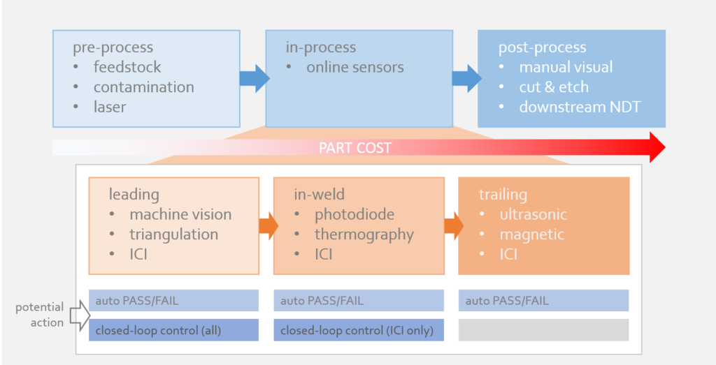
Laser welding checks can be loosely sorted into three subsets: pre-process, in-process and post-process. For now, we’ll use ‘in-process’ checks to refer to any automated measures deployed during the welding process (while the laser is on) but not necessarily measuring the process itself (where the laser hits the metal).
Pre-process checks include steps taken at any stage prior to welding to ensure welds turn out in-spec. Tight control of feedstock and supplier processes are employed to enforce adherence to material standards, but such approaches classically have rapidly diminishing returns on investment and may be outside of a given organization’s power to control. The output of the laser system itself may be monitored with power meters and beam profilers to ensure correct delivery of power to the workpiece. Some sophisticated laser systems tightly integrate laser power delivery with robot motion to further reduce potential process errors.
It’s a generally sound philosophy to try to predict and design out problems rather than react to them, but pre-process checks can’t stand alone. No pre-process measurement can capture all the variables that may influence results, so verification of the results of the process is essential.
Tried-and-true post-process inspection methods such as manual visual surface inspection and destructive testing are still favorites of many laser users who favor their intuitiveness and robustness. Challenges arise due to time, cost and expense, however. Visual inspection provides limited information, and the best measurements from destructive testing can only be practically obtained from a small fraction of finished welds; sometimes at an enormous cost in labor, scrap and lost production.
Automated post-process non-destructive testing exists in the form of x-ray CT, ultrasound and magnetic flux leakage. X-ray builds up highly detailed three-dimensional images of finished welds, including subsurface features, but is too expensive and time-consuming for all but the most specialized applications. EMAT ultrasound uses electromagnetic coupling to both produce and detect an ultrasound source inside ferrous materials. Magnetic flux leakage detects subsurface defects by measuring regions in which magnetic field lines “leak” out of the part as they skirt around voids in the material.
With downstream post-process checks, the most complete information (from sectioning and CT) is also the most difficult to obtain. Destructive testing can only be used on a small fraction of parts, none of which are serviceable after the fact. As an added complication, the further downstream the check is performed, the higher the value of the scrapped parts when defects are found.
A good balance of time and cost savings is found by concentrating checks in-process, using automated sensing equipment. In-process checks can also be sorted into pre- in- and post-weld groupings. In this case the leading (pre) and trailing (post) measurements happen close to the welding process, typically while the welding beam is on. Some in-weld measurements look directly at the point of contact between the welding beam and the material in order to directly sense process dynamics as they unfold.
Sensors that lead the process during welding carry an advantage over earlier pre-process checks in that they are placed at a confluence of weld quality pre-determinants. These sensors can catch errors caused by stock tolerances and fit-up, fixturing and motion control, often with the same measurement. Examples of this kind of sensor include laser triangulation and camera-based systems for seam following. The position of the seam is used in a feedback loop to correct the weld path on the fly.
Trailing sensors allow the finished weld to be assessed before any further value is added to the part, avoiding expensive scrap further downstream. Both ultrasound and magnetic flux leakage are good candidates for immediate, on-line inspection. Laser triangulation is also a popular choice to measure surface topography of the finished weld bead.
For measurement of the process itself, relatively few sensing options exist. The weld process produces intense light across a wide region of the spectrum, blinding traditional cameras without specialized filters. Photodiode sensors make use of these emissions by measuring different bands of optical radiation from the process zone; backscattered light from the welding laser, radiation from the weld plume, or blackbody emissions from the melt region can all be used to assess the weld process. The challenge when implementing these indirect measurements lies in determining which signals correspond to an in-spec weld. The teach-in process for such sensors typically involves lengthy comparisons with destructive testing, and once this stage is complete, the process conditions must remain stable for the sensor to function properly. The relationship between the light coming from process and the shape of the finished weld is complicated.
Thermography is another in-process sensing method that maps the distribution of heat on the surface of the melt pool and weld seam, in order to draw conclusions about subsurface features (e.g., fusion in a lap joint).
Indirect measurements are a useful litmus test for determining whether a process is behaving consistently, but they have their limits. The data often doesn’t provide enough to detail to point to a specific failure mode, or to control process parameters in response to measurements.
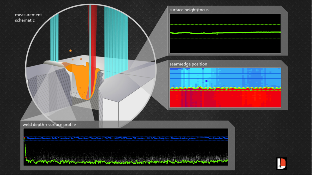
Inline coherent imaging (ICI), an emerging in-process measurement technology patented by Laser Depth Dynamics, measures weld penetration directly at the point where the process laser interacts with the workpiece. This technology is natively compatible with select modern welding heads (e.g., Laser Mechanisms FiberWELD), and retrofits are possible with most common fixed-optic and some scanning-optic heads. ICI makes a time-of-flight measurement with a secondary low-power laser beam, which is immune to blinding by the intense light radiating from the process. This beam is delivered through the same optics as the welding laser, allowing ICI to make direct measurements of the bottom surface of the vapor channel opened by the process laser. This translates into a direct weld penetration measurement. The information produced is similar to the outputs from destructive analysis. Since the measurement occurs during the weld, ICI can be used for automated pass/fail, or even to control the laser power in real time to reach a target depth.

ICI also functions as a leading and trailing in-process measurement. Using a small pair of scanners on the head, the ICI beam can be moved to other regions of the workpiece. This allows collection of seam position and workpiece height data ahead of the welding beam, and imaging of the finished seam surface immediately behind the melt pool. All of these measurements are taken through the head optics, within a few millimeters of the process beam. This suite of quality checks can be performed by a single instrument, by rapidly switching between measurement positions during the weld. The end result is automated pass/fail on any combination of seam position, material height, keyhole depth and finished weld surface, as well as the option to run closed-loop control of laser power and robot motion using the former three measurements. ICI technology provides the most complete automated laser weld monitoring solution to date.
Significant time and cost savings can be realized with advanced in-process sensing. The latest generation of monitoring technology eliminates the need for some downstream tests. The quality assurance for a given weld can often be worked into the existing cycle time. Scrap rates can be cut down through dramatic reduction of destructive tests. Inspection of 100 percent of production welds means entire batches don’t have to fail when defects are discovered, and the direct nature of latest-generation process measurements lowers the theoretical likelihood of false positives when compared with indirect approaches.

The ability to keep a complete, accurate record of production parts is allowing manufacturers to change how they approach quality assurance. It’s now possible to think weld-by-weld instead of batch-by-batch, with unprecedented confidence in the quality of the finished product.
Chris Galbraith is the Applications Specialist and Paul Webster is CTO at Laser Depth Dynamics Inc.20


