Design Guidelines for Laser Metal Deposition of Lightweight Structures
By Ake Ewald and Josef Schlattmann
Introduction
Weight critical applications, like parts in the aerospace industry, are driven by lightweight design. Titanium alloys have great potential in lightweight design of structural parts due to their excellent specific mechanical properties. Today, structural parts are manufactured in conventional milling processes. Titanium parts are characterized by poor milling behaviour as well as high material waste rates up to 95 % [1]. The Laser Metal Deposition (LMD) is a layer-wise manufacturing process for the production of three-dimensional complex parts [2].
LMD builds parts based on a nozzle-fed powder, which is solidified by a laser. The process can be used for surface cladding, repair and build-up of parts. For an effective industrial application, it is necessary to identify all advantages and disadvantages. A lowering of the introduction barrier can be achieved by design guidelines helping the engineer early in the product development. With LMD like Selective Laser Melting (SLM), existing manufacturing guidelines cannot be simply adopted. Due to the complex process constraints, a design guideline for LMD has been established.
Complex parts often share simple geometries as a basis. These shapes were identified and used to evaluate the applicability and effectiveness of LMD. Following established lightweight design guidelines, the presented guideline focuses on fine structures. In addition to the manufacturability, the building accuracy and the surface roughness have been investigated, since both have a significant influence on the product quality and the necessity of post processing towards the final shape of a part.
Investigation of process constraints
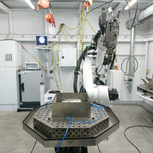
The investigations are performed with a Trumpf TruDisk 6001 multi-mode continuous wave disk laser with a laser power of 6 kW at a wavelength of 1.03 µm. A three nozzle processing head is used with a rotational table feeder (Fig. 1). The used Ti-6Al-4V powder is spherical and sieved to a fraction less than 80 µm.
Three different building strategies have been identified in a preliminary design guideline by Möller et al., 2016 [3]. Figure 2 shows the different building strategies. In S1 an inclination is achieved by a stepwise offset (a) between the layers (α = β = 0°). S2 rotates the platform to reach the inclination. The structure is manufactured vertically without an offset between the layers. S3 rotates the machine head to the inclination angle of the structure. The structure can be manufactured without an offset. Besides the three single building strategies, combinations of these are possible, which are not considered at this point. The preliminary guideline published by Möller et al. (2016) showed a high potential in the degree of freedom of building strategy S2 and S3 [3]. For this reason, these strategies were further investigated.

The mentioned fine structures have been classified as thin walls, curved walls, congregating and aggregating structures. The width of the manufactured structures has been set to a single layer width. The length has been set to 50 mm.
Thin Walls
The build-up of inclined thin walls has been made to investigate
- the connection towards the platform,
- the influence of the gravitation,
- the building accuracy and
- the influence on the wall surface.
Both strategies produce a constant and comparable wall thickness under (see Fig.3). It varies due to the surface roughness of about 150 µm. The variation of the measured angle is less than 1°.
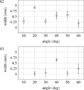
The surface quality of a part has an influence on the appearance, the buy to fly ratio in case of a post processing, and the fatigue strength. The mean values of the surface roughness remain constant with rising inclination angles. The surface roughness of S3 is about 15 µm higher than with S2.
Curved Walls
Curved walls can vary in radius and angle. Curved walls can be divided into curves with their rotational axis parallel, and perpendicular to the building direction (z-axis, Fig. 4). The vertical built up of the curved walls with different radii can be seen in fig. 5.

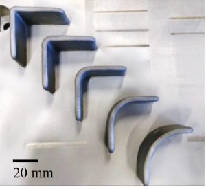
The radii of the built walls are 0.15 mm to 0.4 mm smaller than expected. An intended vertical edge (radius of 0 mm) produces an outer radius of 3.58 mm. Without post processing, edges should be designed to allow a radius up to the layer width. The radius independent deviation allows the manufacturing in reproducible tolerance fields.
Congregating and Dividing Structures
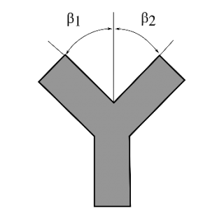
The separation in congregating and dividing structures is based on the necessity of different manufacturing strategies and constraints in LMD (Fig. 6).

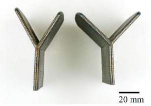
The manufacturing of regular and reversed Y-branches was realised by using S3. To achieve good results, binding on alternating branch sides is recommended (Fig. 7).
Additionally, overhangs were built on the manufactured vertical wall (Fig. 8) to evaluate
- the connection between a thin rough wall and a manufactured wall,
- the building accuracy, and
- the boundary constraints.
The measured angles of the overhangs have an angle deviation of less than 1° up to a manufacturing angle square to the gravity (Tab. 1). This is comparable to the inclined walls. Overhangs show that overhangs with the same or smaller width can be manufactured on thin walls.
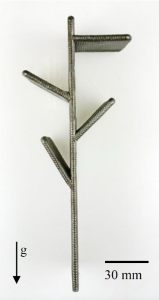
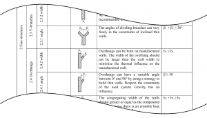
Table 1 Measured inclination angles of the manufactured overhangs. The guidelines derived from the experimental investigation have been collected in a design catalogue according to the VDI 2222 in extracts shown in the figure 9.
Conclusion and Outlook
LMD offers a high degree of freedom in the design of parts. Lightweight parts can benefit from this flexibility. An industrial application can be achieved by design guidelines helping engineers to take the advantages and disadvantages of the LMD process into account during the design process.
The experimental investigation points out that structures based on the basic shapes are producible with constant geometric and surface tolerances, which allows reliable final machining. This is the basis for a successful design process. The building strategy S2 and S3 can be applied. The comparable results of S2 and S3 allow to choose the better fitting strategy for a specific use case.
By focusing on lightweight application, the following aspects have been achieved:
- Investigation and manufacturing of basic shapes
- Determination of process constraints
- Draft of a design guideline.
The developed design catalogue builds a first step towards a comprehensive design guideline for LMD.
M.Sc. Ake Ewald has been a research assistant in the workgroup System Technologies and Engineering Design Methodology at the Hamburg University of Technology since 2013. He works in the methodical product development where he researches the methodical design of hybrid manufactured structural parts using LMD.
Josef Schlattmann is Univ.-Professor at the Hamburg University of Technology. He leads the workgroup System Technologies and Engineering Design Methodology.
References
[1] Allen, J. (2006) An Investigation into the Comparative Costs of Additive Manufacture vs. Machine from Solid for Aero Engine Parts, Rolls-Royce PLC Derby, UK.
[2] Ravi, G.A., Hao, X.J., Wain, N., Wu, X., Attallah, M.M. (2013) Direct laser fabrication of three dimensional components using SC420 stainless steel, Materials & Design, Vol. 47, 731-736.
[3] Möller, M., Baramsky, N., Ewald, A., Emmelmann, C., Schlattmann, J., (2016) Evolutionary-based Design and Control of Geometry Aims for AMD-manufacturing of Ti-6Al-4V Parts, Laser Assisted Net Shape Engineering 9 International Conference on Photonic Technologies Proceedings of the LANE 2016, S. 733–742, DOI: 10.1016/j.phpro.2016.08.075.


