By: Christophe Arnaud, Charly Loumena, Rainer Kling
Surface preparation can have different properties for a large field of applications in very different industries.
Polishing a surface can avoid unsightly defects on mold parts, or can provide very smooth surfaces for finished products. Since actual ablation processes are time-consuming, can create dust and at times involve chemical treatment, a new approach of using direct laser surface modification has a great market potential.
Industrial fiber lasers can be competitive by melting and smoothing the surface up to 20 times faster than conventional techniques, and their costs are lower than pulsed lasers.
But sometimes surfaces need to be machined to replicate patterns on a part. This method is often used in various industries such as automotive (for dashboards) and injection molding. Laser ablation is already used to design complex patterns but their ablation rates are low: Nanoseconds lasers obtain volume rate ablation close to 1mm3/s but laser remelting can reallocate metal and create a pattern 30 times faster without the need of finishing process due to the surface tension the resulting surface has a polished like finish.
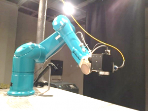
The setup is quite industrial with a fiber laser from IPG (YLR 300/3000 QCW -1070 nm multimode, 300CW, 0.1-10 ms) plugged into a PRECITEC F100 collimator and mounted onto a SCANLAB Hurryscan III 14mm galvanometer scanning head providing a scanning speed up to 2.5 m/s.
To obtain a full 3D solution, the scanner has been mounted on a STÄUBLI Robot (TX90-L) which can treat parts within volumes up to 1 m3.
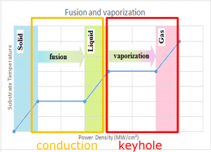
The optical configuration and the control of the laser power allow the user to determine the metal modification. With low or modest laser power density that irradiates the sample, the metal reaches melting temperature, whereas at high power density vaporization temperature is reached. These two different temperature profiles will lead to conduction mode melt formation or keyhole formation, respectively (Figure 2).
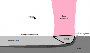
Polishing metal is achieved by irradiating the sample with a laser beam in order to melt a thin metal layer. Therefore, the melted metal peaks fill the valleys, and when solidifying, the surface tension smooths the metal hence reducing the roughness (Figure 3).
If the laser power is not constant during the processing, the melt pool volume varies as the power increases or decreases (Figure 4). Furthermore, due to changes from solid to a liquid phase and the thermal dilatation, the melt pool surface bulges outward. By this way, patterns can be created by modulating the laser power.
Plenty of parameters were tested on stainless steel (304L) in order to identify the main trends, to obtain the melting pool and to reduce roughness. The first goal was to find the best line overlap. Experiments were made for laser power from 50 W to 150 W, while overlap varies from 60% to 90%. The best operating range was identified for overlaps between 80% and 90% (Figure 5).
Secondly, by tuning laser power and beam diameter, the laser power density varies. We underline that best results are obtained with power density from 0.8 to 1.2×10⁶ W/cm² which corresponds to conduction mode welding. While increasing the laser power density, keyhole welding quickly appears resulting in higher roughness (Figure 6).
The third main parameter affecting roughness was identified to be the number of scans (Figure 7). Multiscans can slightly reduce the final roughness, and best results are obtained by crossing the hatch by 90°.
Applying these main parameters on surfaces with varying degrees of roughness produces smoother surfaces. Bright surface aspects are obtained with processing times from 20 s/cm² to 200 s/cm² depending on the initial roughness.
On high roughness parts with a Sa value of 6.4 µm (Figure 8), the roughness can be reduced by 10 within a processing time of 200 s/cm². This could be a good way to pre-reduce the roughness in a very short processing time. In this case, the heat affected zone is around 320 µm.
On most common milling parts roughness is around 2 µm (Figure 9). In this case, processing time is close to 100 s/cm², and the heat affected zone is reduced (around 35 µm). Laser polishing can then reduce the roughness by 8 times, producing bright surfaces (Figure 10) and can find applications in fine polishing to obtain reflective surfaces.
As the laser treatment possesses a high resolution, selective polishing can be made to create high contrast for patterning and writing texts to preserve sharp edges on a part and reach areas with difficult access where conventional tools cannot be employed. This versatile solution can produce details around 1 mm² and find decorative applications.
This case was tested on a sandblasted Aluminum surface whose roughness has been reduced by 10 (Figure 11) resulting in a very reflective surface (Figure 12).
Laser polishing offers various possibilities in pre-polishing or fine polishing in many applications from molds (injection, glass, etc.) to decoration.
According to the previous observations on polishing metals, laser power density can vary between the melting point and vaporization point to control the melting pool volume and imprint into the metal surface a 3D pattern by reallocation of the melt volume and resolidification in different locations.
In the first modulation profile, we apply full laser power along the first millimeter, then the laser is switched off along the following four millimeters (Figure 13). The peak height is measured from laser powers ranging from 50 W to 250 W and swipe numbers from 1 to 50 (Figure 14).
The peak height increases with the laser power and the swipe number, but above a power of 150 W and for swipe numbers over 10 swipes, the peak height decreases due to heat accumulation. In order to enhance the buildup, experiments are made with a new power modulation profile. Now, laser power decreases along a distance, ‘d’, from 1 to 10 mm (Figure 15).
By using this new power profile and 10 swipes, the peak is still growing over 150 W for distances over 5 mm. For shorter distances, heat accumulation is observed, which reduces the peak height (Figure 16).
To avoid heat accumulation influence, a delay between each swipe is introduced for 200 swipes and laser power of 250 W (Figure 17). Without any delay, the peak height reaches 1 mm. However, introducing a 100 ms delay results in the height growing by 25%, and by 50% with a 300 ms delay. The peak’s shape without delay is rounded, with oxidation and spatters around, meaning that the welding process turned into keyhole mode welding due to heat accumulation (Figure 18 left). With a delay or oxidation, the peak is higher and the shape is like the power modulation profile (Figure 18 right).
Modulating the laser power combined with a scanning strategy permits the creation of complex patterns (Figure 19) up to 30 times faster than by laser ablation processes.
Fiber lasers are perfectly adapted for polishing with good results in a very short processing time. Depending on the initial roughness, the processing time varies but can be approximately 20 times shorter than conventional processes, and the remelting produces no dust or other side effects that require posttreatment.
By modulating the laser power, it provides a low-cost alternative in comparison to short/ultrashort pulsed laser for engraving and patterning applications with processing speeds that are 30 times faster, while keeping the polished appearance directly after the pattern generation. Depending on the strategy, we can create a micro structure (some µm) and macrostructure (over millimeter) topographies.
Christophe ARNAUD christophe.arnaud@alphanov.com is a technician in the laser micromachining business unit at ALPhANOV working on meso-scale laser processes.


